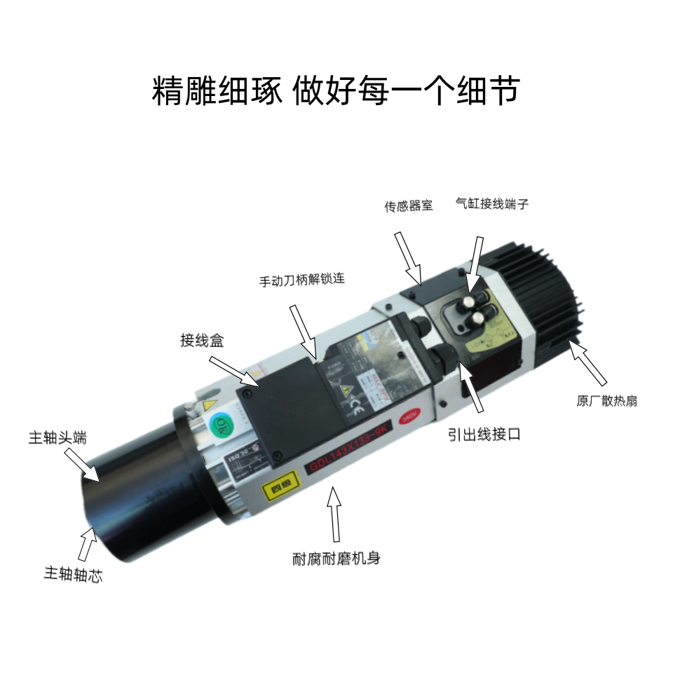
The 9 kW automatic tool-changing spindle is a core component of engraving machines and machining centers. It must be operated strictly in accordance with specifications; otherwise, it may lead to spindle seizure, reduced precision, or bearing damage.
I. Pre-Startup Inspection
1. Cooling System (Water-Cooled)
- Ensure the circulating cooling water flows smoothly, with a flow rate of ≥5 L/min
- Optimal water temperature: 20±2°C; water must be clean and treated with rust inhibitor
- Check that water hoses are free of leaks, kinks, and blockages
2. Pneumatic System (for Tool Change)
- Air supply pressure: 0.5–0.7 MPa; air must be dry, oil-free, and water-free
- Check that the air filter/regulator/lubricator unit is properly drained and has normal oil levels
3. Spindle and Tool Holder
- Tapered bores (BT30/40) must be clean: free of metal shavings, oil residue, and dents
- Tool holders and set screws must be intact; tapered surfaces must be clean; installation must be secure
- Manually test tool insertion: confirm that clamping and releasing actions are smooth
4. Electrical System and Inverter
- Inverter power ≥ 11 kW (1–2 ratings higher than the spindle)
- Voltage, frequency, and V/F curve match the spindle nameplate
- Verify rotation direction (counterclockwise from the front end is correct); if direction is incorrect, stop immediately and reverse the phase
II. No-Load Warm-Up (Critical! Protects bearings)
- Run at low speed (3000–5000 rpm) under no-load conditions for 5–10 minutes
- Observe: No abnormal noise, no severe vibration, normal temperature (≤ ambient +40°C)
- After warm-up: Manually change tools 3–4 times to confirm normal tool release/gripping with no jamming
III. Automatic Tool Changer (ATC) Operating Procedures
Core Rule: Tool changing must only be performed when the spindle is completely stationary (0 speed)
1. Automatic Tool Changing (Program M6)
- Program runs to the tool change point (Z-axis safety height)
- System detects spindle speed 0 signal → Executes tool release (cylinder pushes open)
- Tool magazine rotates → Spindle lowers to pick up tool → Tightens → Confirm in place
- After tool change, verify tool offsets and confirm clamping before resuming machining
2. Manual Tool Change
- Stop the spindle → Press the tool release button on the control panel → Remove the old tool
- Insert the new tool → Release the button → Confirm that the tool is securely clamped in place (a distinct “click” should be heard)
- Strictly prohibited: Changing tools while the spindle is not stopped, forcibly inserting or removing tools, or striking the tool shank
IV. Machining Operation Guidelines
- Do not operate under high load when the machine is cold: Preheat first, then gradually increase speed and load
- Match speed to load: A 9kW spindle typically operates at 8,000–18,000 rpm; do not exceed the rated maximum speed
- Coolant: Direct coolant flow toward the cutting area of the tool; do not spray directly onto the spindle face or the collet
- Monitor operating conditions:
- Temperature Rise: Housing temperature ≤ 60°C
- Noise: Smooth operation, no abnormal sounds or screeching
- Vibration: No noticeable shaking
- Immediately perform an emergency stop and troubleshoot any abnormalities
V. Shutdown and Daily Maintenance
1. Shutdown Sequence
- Stop machining → Let the spindle idle for 1–2 minutes to dissipate heat → Stop the spindle
- Turn off coolant → Turn off pneumatic system → Shut down the system → Turn off main power
2. Daily Cleaning
- Wipe the spindle taper bore and end face with cotton paper or non-woven cloth, then apply a small amount of rust-preventive oil
- Blow away chips and coolant to keep the area around the spindle clean
3. Periodic Maintenance (Critical)
- Every 500 hours: Replace spindle-specific grease (high-temperature, high-speed grease)
- Every 1,000 hours: Check radial runout (≤0.002 mm)
- Weekly: Inspect cooling/pneumatic filters and clean filter elements
VI. Strictly Prohibited Actions (Red Lines)
- ❌ Changing tools while the spindle is running (will cause seizure)
- ❌ Installing tools with contaminants in the taper bore (compromises accuracy and prevents secure clamping)
- ❌ Performing high-speed heavy-duty cutting on a cold machine (will burn out bearings)
- ❌ Forced operation beyond rated speed, power, or torque limits
- ❌ Striking the spindle, tool holder, or clamping jaws
- ❌ Forced operation with interrupted coolant or abnormal pneumatic systems
VII. Common Issues
- Tool change jam: Usually caused by changing tools without stopping, a dirty taper bore, or insufficient air pressure
- Excessive heat: Insufficient cooling, lack of lubrication or degraded lubricant, bearing wear
- Vibration/abnormal noise: Poor dynamic balance, tool runout, bearing damage
- Tool not clamped securely: Loose retaining pins, fatigued disc springs, insufficient cylinder pressure
888 Huaihe West Road, Huangdao District, Qingdao City, Shandong Province
Copyright © 2025 by Shandong Longchi Electric Motor Co., Ltd. All Rights Reserved

